Gensol's team of Electrical,Mechanical & Civil Engineers and Draughtsmen are adept at designing and vetting Solar Engineering Drawings, calculations and quality procedures.Detailed Engineering encapsulates the power of preparing optimized plant designs in the best interest of gaining optimized plant performance as per the best practices.
- Basic Drawings
- Field & Material Quality Procedures
- As built Drawings
- Detailed Drawings
Gensol has an experience of over 1470+ MW Solar PV Design Engineering. This service covers basic engineering for the purpose of establishing conceptual design to ensure that the planned technical approach will meet the requirements. Based on the concepts, whole detailed engineering is performed in order to ensure that the design implementation has met all the requirements for the installation.
Solar Electrical DC (Pre Inverter)
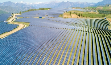
PROJECT LAYOUT
- Shadow losses can be significant depending on distance between modules
- Location of inverters can significantly control costs and losing cables
STRING COMBINER BOX
- Inappropriate fuse rating poses risk to the modules and inverters
- Enough redundancy ensures higher equipment uptime
- IP protection is essential to withstand the vagaries of nature
- Busbar sizing is critical to the safety of the equipment
CABLE SIZING
- Increases cost and losses if inappropriately sized
- UV protection and conduiting to prevent degradation because of exposure
SCADA SYSTEM
- Monitoring at micro level ensures the accurate energy generation measurement and detection & retification of faults in minimum time.
Solar Electrical AC (Post Inverter)
Transformer Rating
- Can lead to loss in energy generation in case it is not sized optimally
- Enough redundancy ensures higher equipment uptime
LT AND HT PANELS
- Appropriate relays ensure the maximum protection of the plant and detection of faults
- CT /PT Ratios need to follow the approved grid requirements
CONDUCTOR SIZING
- Increases costs and losses in case of inappropriate sizing
- Appropriate protection in accordance with design fault current
Civil & Structural Drawings
LAND DEVELOPMENT
- Should be in accordance to the Topographic survey to minimize cutting/ filling and nevertheless provide similar heights for structures in a row
MODULE MOUNTING STRUCTURE
- Should have correct clearance from the ground
- Should be designed according to the wind and seismic zone of the site
COMMON FACILITIES
- Access roads should be provided in accordance to the shape of the land to ensure access to the whole plant particularly for heavy vehicles
- Drainage should be designed as per the rain pattern of the location and have slope according to the final drain outlet of the plant
INVERTER & CONTROL ROOM
- Provision of natural/ forced ventilation
 Search

 800 MW
 3583 MW